Due to a recent bug fix with output power. Please make sure you are running version 1.8 or newer of the mini clock config software.
This module allows locking the ICOM IC-9700 radio transceiver internal frequency reference, to an external 49.152MHz signal. If the internal reference is locked to a GPS signal, achievable ICOM stability can be better than 1Hz on all bands.
Installing this module inside the ICOM IC-9700 does not require any soldering or modification to internal circuitry. This modification is completely reversible and should not affect your warranty.
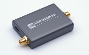
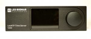
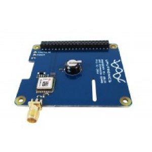
This module is designed to be used and has been tested with the Leo Bodnar GPS reference clocks signal sources.
Step-by-step Installation Instructions
Disconnect all external cables and wires connected to the IC-9700
Place a soft cloth or clean towel on your working surface to avoid scratching your ICOM IC-9700
Remove 12 cross-head screws holding the bottom cover - three on each side and six on the bottom. Use the correct screwdriver to avoid stripping screw heads
Turn IC-9700 upside down, remove the bottom cover and put it aside
Unscrew the nut holding SMA connector on the back marked "REF IN 10MHZ". Disconnect small U.FL connector, remove and save the cable. Alternatively, leave U.FL side connected, place SMA connector, nut and washer into a small plastic bag and securely tape it inside the IC-9700
Remove black airflow protection sponge and stick it elsewhere inside the IC-9700
Remove two screws on the main PCB, marked "10" and "11". Put them aside
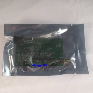
Install injection board using two supplied longer screws
Place old screws into two holes on the injection board for storage
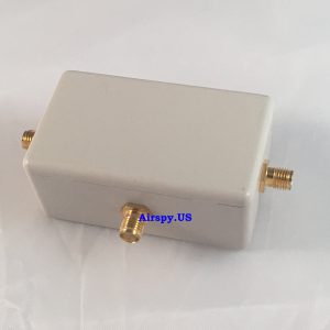
Install SMA extension cable between the injection board and the connector previously used by "REF IN 10MHZ" (cable is supplied.)
Install bottom cover and fix it with twelve screws
ICOM IC-9700 Setup Instruction
Configure your GPS clock to output 49152000Hz signal with full power (32mA setting)
Connect the clock source to SMA connector on the back of IC-9700 (Cable not supplied)
Turn IC-9700 on and let it warm up for 5-10 minutes
Switch to a SSB mode and tune to a reasonably stable CW signal you can hear and see on the waterfall
Press MENU button then tap (1), SET, Function, REF Adjust
Turn on external 49.152MHz reference and observe CW signal frequency shift. Adjust sliders so that frequency shift is within 10Hz on 2m band (30Hz on 70cm band or 100Hz on 1200MHz band.)
Exit the menu and test IC-9700 operation.
Troubleshooting - if IC-9700 does not lock
Make sure external reference is switched on, has correct 49.152MHz frequency and 10-20dBm power level
Verify that REF Adjust is set correctly. Coarse scale should be roughly in 40-50% range. Follow fine adjustment procedure above.
Lock range for proper set up is wider than 100Hz (2m band), 300Hz (70cm band), 800Hz (1200MHz band) in both direction. This is about two times wider than extreme excursion during continuous transmit and receive periods.


Reviews
There are no reviews yet.